Ieaskul F. Mobenthey Sprott
- Regular price
- $333.00
- Sale price
- $333.00
- Regular price
-
- Unit price
- per
The Sprott module is a model of chaotic jerk system with standardized voltage control of all parameters. Thus, the chaotic attractor can be shrank down to distill the module into a resonant filter that is the dynamical sub- circuit underlying most jerk systems. It is named after J.C. Sprott who has published numerous papers, articles and books on chaos and chaotic circuits, from a rigorous physical view-point. This module is of course for musical purposes; although the voltage control feature has limited import in physics experiments, it is crucial to aesthetic purposes.
Sprott is an 8HP Eurorack module that runs on +12 and -12 volts. Attach power connector positive to “+” and negative to “-”. Failure to follow proper power polarity will result in instant destruction of unit.
Sprott has three integrators and one “signum” non-linearity, according to the simple differential equation, “0 = ax''' + bx'' + cSGN(x) – dx”. In re-structuring the circuit to fit voltage control guidelines, the use of transconductance amplifiers offers an experimental input to change the subtle dynamics of this system: by modulating their linearizing diodes, paradoxically adding to non-linearities available. The module is thus for experimentation, but it can always boil down to a simple resonant filter, perhaps this is its power, in going out and coming back to a basic regime. Since any differential jerk equation is highly dependent on “initial parameters,” Sprott has a dedicated VCA on the input.
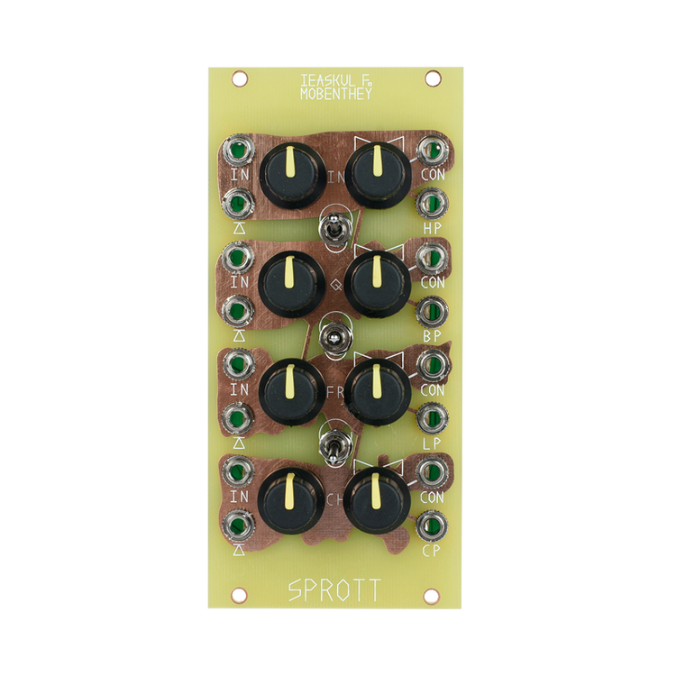
Use of this VCA can help inform use of the other three sections. Looking at the front panel of Sprott, note that inputs are marked by copper fill. For any section there is an “in” and a “diode”. The in inserts signal energy directly into that portion of the differential equation, with the VCA inserting directly into the high-pass. It should be mentioned, however, that inputting into one section will affect all; they are not separate filters but all inter-connected as per the equation. The diode is the least explainable of all inputs, but just note that a higher voltage here will in general bring the frequency down, but it should also bring it into a more linear mode of operation. As Ieaskul said, it is experimental. The VCA has a basis knob, on the left, which sets a basic amplitude for its input. It then has the VCA control input and associated attenuverter which modulate it furthermore.
An attenuverter works like this: at noon the modulations are nulled out, they have no effect; clockwise from there they increase in intensity, with positive input meaning “more”; to the counter-clockwise direction, modulations increase as well, but with negative input meaning “more”. This knob is essential to controlling how much, and in which direction, your modulations apply.
For each section, there is an output that reflects one part of the differential equation, in the natural order it is built in circuitry. So, from top-down, there are high-pass, band-pass, low- pass, and finally, chaos-pass outputs. Each section has it's own range switch. When in middle position, the section runs at a standard audio rate. Pointing downward is a low audio rate, and pointing upwards is a definite CV, lowest rate. They are separated for experimentation purposes, however standard operation is to have them set at the same range- all up, all mid, or all down.
The next section is labeled, “Q,” meaning voltage control of quality, or resonance. It has a similar “in,” “diode,” “control,” and knobbage structure. The “Q” is highest when this knob is down, and that can cause saturation of the waveform allowing experiments in distorted filtering. For sweet filtering purposes, turn “Q” up later than noon.
The next section down is labeled “FR” for “frequency”. Here is where the general time-dependance is modulated, also known as “cutoff” in filterland. It too has a similar knobbage/jackage structure.
Finally the bottom section is devoted to chaos, through control of the “third integral”. It has a similar jack structure, and it should be pointed out that the knobs control how much chaos is inserted back into the dynamic. With its basis knob all the way down, Sprott should return happily to filterland.
To read more about Jerk Equations, please consult J.C. Sprott's massive corpus of publications at:
http://sprott.physics.wisc.edu/pubs.htm
Sprott is an 8HP Eurorack module that runs on +12 and -12 volts. Attach power connector positive to “+” and negative to “-”. Failure to follow proper power polarity will result in instant destruction of unit.
Sprott has three integrators and one “signum” non-linearity, according to the simple differential equation, “0 = ax''' + bx'' + cSGN(x) – dx”. In re-structuring the circuit to fit voltage control guidelines, the use of transconductance amplifiers offers an experimental input to change the subtle dynamics of this system: by modulating their linearizing diodes, paradoxically adding to non-linearities available. The module is thus for experimentation, but it can always boil down to a simple resonant filter, perhaps this is its power, in going out and coming back to a basic regime. Since any differential jerk equation is highly dependent on “initial parameters,” Sprott has a dedicated VCA on the input.
Use of this VCA can help inform use of the other three sections. Looking at the front panel of Sprott, note that inputs are marked by copper fill. For any section there is an “in” and a “diode”. The in inserts signal energy directly into that portion of the differential equation, with the VCA inserting directly into the high-pass. It should be mentioned, however, that inputting into one section will affect all; they are not separate filters but all inter-connected as per the equation. The diode is the least explainable of all inputs, but just note that a higher voltage here will in general bring the frequency down, but it should also bring it into a more linear mode of operation. As Ieaskul said, it is experimental. The VCA has a basis knob, on the left, which sets a basic amplitude for its input. It then has the VCA control input and associated attenuverter which modulate it furthermore.
An attenuverter works like this: at noon the modulations are nulled out, they have no effect; clockwise from there they increase in intensity, with positive input meaning “more”; to the counter-clockwise direction, modulations increase as well, but with negative input meaning “more”. This knob is essential to controlling how much, and in which direction, your modulations apply.
For each section, there is an output that reflects one part of the differential equation, in the natural order it is built in circuitry. So, from top-down, there are high-pass, band-pass, low- pass, and finally, chaos-pass outputs. Each section has it's own range switch. When in middle position, the section runs at a standard audio rate. Pointing downward is a low audio rate, and pointing upwards is a definite CV, lowest rate. They are separated for experimentation purposes, however standard operation is to have them set at the same range- all up, all mid, or all down.
The next section is labeled, “Q,” meaning voltage control of quality, or resonance. It has a similar “in,” “diode,” “control,” and knobbage structure. The “Q” is highest when this knob is down, and that can cause saturation of the waveform allowing experiments in distorted filtering. For sweet filtering purposes, turn “Q” up later than noon.
The next section down is labeled “FR” for “frequency”. Here is where the general time-dependance is modulated, also known as “cutoff” in filterland. It too has a similar knobbage/jackage structure.
Finally the bottom section is devoted to chaos, through control of the “third integral”. It has a similar jack structure, and it should be pointed out that the knobs control how much chaos is inserted back into the dynamic. With its basis knob all the way down, Sprott should return happily to filterland.
To read more about Jerk Equations, please consult J.C. Sprott's massive corpus of publications at:
http://sprott.physics.wisc.edu/pubs.htm
The Sprott module is a model of chaotic jerk system with standardized voltage control of all parameters. Thus, the chaotic attractor can be shrank down to distill the module into a resonant filter that is the dynamical sub- circuit underlying most jerk systems. It is named after J.C. Sprott who has published numerous papers, articles and books on chaos and chaotic circuits, from a rigorous physical view-point. This module is of course for musical purposes; although the voltage control feature has limited import in physics experiments, it is crucial to aesthetic purposes.
Sprott is an 8HP Eurorack module that runs on +12 and -12 volts. Attach power connector positive to “+” and negative to “-”. Failure to follow proper power polarity will result in instant destruction of unit.
Sprott has three integrators and one “signum” non-linearity, according to the simple differential equation, “0 = ax''' + bx'' + cSGN(x) – dx”. In re-structuring the circuit to fit voltage control guidelines, the use of transconductance amplifiers offers an experimental input to change the subtle dynamics of this system: by modulating their linearizing diodes, paradoxically adding to non-linearities available. The module is thus for experimentation, but it can always boil down to a simple resonant filter, perhaps this is its power, in going out and coming back to a basic regime. Since any differential jerk equation is highly dependent on “initial parameters,” Sprott has a dedicated VCA on the input.
Use of this VCA can help inform use of the other three sections. Looking at the front panel of Sprott, note that inputs are marked by copper fill. For any section there is an “in” and a “diode”. The in inserts signal energy directly into that portion of the differential equation, with the VCA inserting directly into the high-pass. It should be mentioned, however, that inputting into one section will affect all; they are not separate filters but all inter-connected as per the equation. The diode is the least explainable of all inputs, but just note that a higher voltage here will in general bring the frequency down, but it should also bring it into a more linear mode of operation. As Ieaskul said, it is experimental. The VCA has a basis knob, on the left, which sets a basic amplitude for its input. It then has the VCA control input and associated attenuverter which modulate it furthermore.
An attenuverter works like this: at noon the modulations are nulled out, they have no effect; clockwise from there they increase in intensity, with positive input meaning “more”; to the counter-clockwise direction, modulations increase as well, but with negative input meaning “more”. This knob is essential to controlling how much, and in which direction, your modulations apply.
For each section, there is an output that reflects one part of the differential equation, in the natural order it is built in circuitry. So, from top-down, there are high-pass, band-pass, low- pass, and finally, chaos-pass outputs. Each section has it's own range switch. When in middle position, the section runs at a standard audio rate. Pointing downward is a low audio rate, and pointing upwards is a definite CV, lowest rate. They are separated for experimentation purposes, however standard operation is to have them set at the same range- all up, all mid, or all down.
The next section is labeled, “Q,” meaning voltage control of quality, or resonance. It has a similar “in,” “diode,” “control,” and knobbage structure. The “Q” is highest when this knob is down, and that can cause saturation of the waveform allowing experiments in distorted filtering. For sweet filtering purposes, turn “Q” up later than noon.
The next section down is labeled “FR” for “frequency”. Here is where the general time-dependance is modulated, also known as “cutoff” in filterland. It too has a similar knobbage/jackage structure.
Finally the bottom section is devoted to chaos, through control of the “third integral”. It has a similar jack structure, and it should be pointed out that the knobs control how much chaos is inserted back into the dynamic. With its basis knob all the way down, Sprott should return happily to filterland.
To read more about Jerk Equations, please consult J.C. Sprott's massive corpus of publications at:
http://sprott.physics.wisc.edu/pubs.htm
The Sprott module is a model of chaotic jerk system with standardized voltage control of all parameters. Thus, the chaotic attractor can be shrank down to distill the module into...
Width: 8HP
Power: 12mA @+12V, 12mA @-12V, 0mA @+5V
Questions
Have any questions? We're here to help!